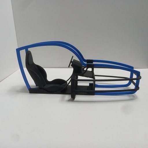
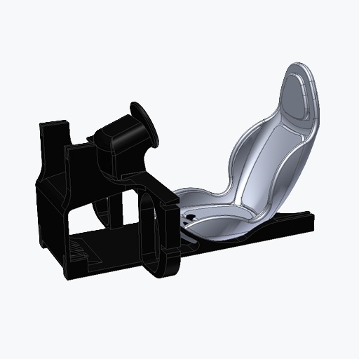
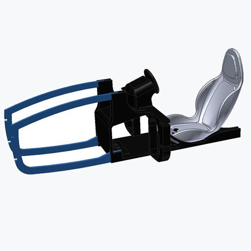
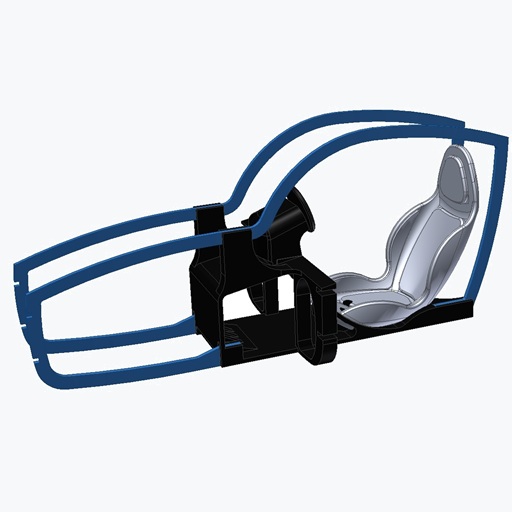
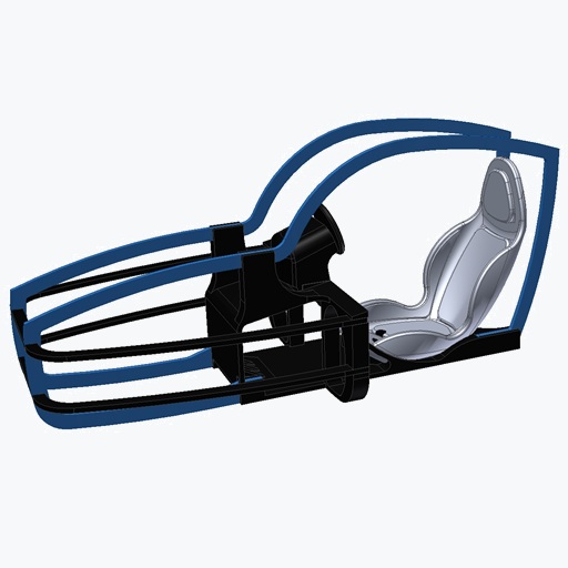
The cockpit of the MidiMotionRig is intentionally kept simple. It is not intended to be a scale model of a sim racing cockpit, but rather a stylized representation of the key elements of a motion platform. The steering wheel, pedals, racing seat, and simplified bodywork follow the typical design language of a sim racing vehicle, making the intended purpose of the platform immediately recognizable.
Despite its deliberately simplified appearance, the model already provides a good impression of the future motion platform and gives the MidiMotionRig its distinctive character.
The individual parts are assembled using plastic adhesive. For this project, I used Evonik Acrifix 1R 0192. During curing, the parts can be securely held in position using simple clothespins.
Technical Data:
- Dimensions: 334 × 150 × 146 mm (L × W × H)
- Assembly: Bonding of individual parts using plastic adhesive
- Mounting: 4 × M3×12 screws and spacers for later installation on the Surge axis
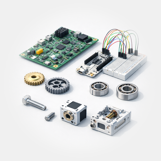
Matching Components for the Cockpit
If you want to recreate the Workshopboard without spending time searching for parts, you will find the key components here that were used exactly in this setup.
The complete parts list, including dimensions, quantities, and standardized components, is also available as a PDF.
Affiliate link: As an Amazon Associate, I earn from qualifying purchases.
Step-by-Step Assembly Guide
Step 1 – Installing the Beltline
Begin with the cockpit base part (3DOFP-00-07) and the two beltline components (3DOFP-00-14). Bond the parts together using plastic adhesive.
For holding the parts in place while the adhesive cures, clothespins have proven to be a simple and practical solution.
Depending on the adhesive used, the curing time is approximately 20 minutes.
My first attempt using cyanoacrylate adhesive was unsuccessful. The plastic adhesive provides significantly better results for this application.
Step 2 – Installing the Roofline
The two roofline components are assembled in the same way and should also be secured until the adhesive has fully cured.
Step 3 – Installing the Plan Shape Elements
Finally, install the two plan shape elements. Apply a small amount of adhesive into the designated recesses and carefully slide the parts into position.
Step 4 – Preparing for Installation
The spacers and the four M3×12 screws are required for the later installation of the cockpit onto the Surge axis.
Additional Datas:
Drawing
PDF-BoM