- Midi Motion Rig: Cockpit
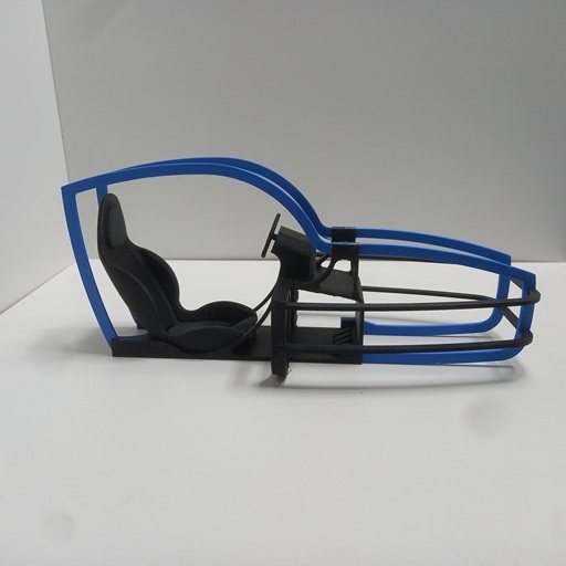
At last, the MidiMotionRig is making the transition from an idea that existed only in CAD into the real world. In fact, it has already been a few days since I printed and assembled the cockpit for the MidiMotionRig. Even so, I would like to give it a brief introduction here.
Over the next few days, the cockpit will be added to the project documentation as the first completed subassembly. As always, the corresponding files and information required to recreate it will also be made available.
If you would like to see how the cockpit came together, feel free to check out the build videos on Instagram and TikTok. You can find the relevant links further below.


- The MidiMotionRig Project Begins
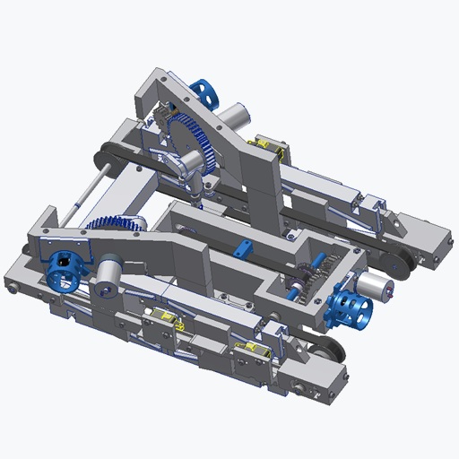
The design phase of the MidiMotionRig has finally been completed.
After many hours of CAD work, the project now enters the actual construction phase of a mechanical puzzle consisting of a total of 874 individual parts.The project will be built and documented step by step — starting with the base linear axis, followed by the 2DOF, 3DOF, and 4DOF versions, all the way to the final 6DOF configuration.
Just like the NanoMotionRig, the MidiMotionRig follows a consistently modular design approach.
This makes it possible to develop, test, and expand the mechanics, electronics, and software gradually over time.But why build a MidiMotionRig in the first place?
While the NanoMotionRig was primarily intended as a simple introduction to motion platforms, the MidiMotionRig pursues a much larger goal:
the development and optimization of a complete motion-control platform at a compact scale.The system makes it possible to test and further develop electronics, sensor systems, and Arduino software on a complete 6-axis setup — without immediately having to build the large and expensive mechanical components required for the later full-scale, human-carrying version. Changes in control behavior or software can therefore be observed and evaluated directly.
During the design process, particular attention was also given to achieving axis dynamics and speed characteristics that behave as closely as possible to the later FullMotionRig version. Many electronic components, such as the Arduino Mega 2560, Hall sensors, limit switches, and safety systems, can later be transferred almost one-to-one into the larger system.
The goal of the MidiMotionRig project is therefore not only to create another fully functional desk-sized motion platform, but also to establish the hardware and software foundation for the later full-scale FullMotionRig.
At the same time, the project is intended to make the topic more accessible for others. Electronics, sensor systems, and motion control can be explored and tested in a practical way without immediately investing large amounts of money into oversized mechanical components.
With the start of the MidiMotionRig, this marks not only the beginning of a new motion project, but also the foundation for the next development stage of the future FullMotionRig.
- Small Footer Update
The WorkshopTales social media channels are now directly accessible through the footer.
YouTube, Instagram, and TikTok provide additional insights into CAD development, testing, and smaller project updates between the larger posts.
- Midi Motion Rig Update
The current state of the motion rig project is still clearly in the design phase, but recent iterations have led to a fundamental insight: the previous approach to the axis drives has been completely discarded and is now being rethought from the ground up.
The focus is no longer solely on mechanical implementation, but specifically on the dynamic behavior of the axes. The goal is to achieve motion characteristics in the mockup that are as close as possible to the later full-scale, human-carrying version. In practical terms, this means high travel speeds, short response times, and a direct, responsive system behavior.
A key decision is the clear separation between mechanics and function. The mockup is not intended as a simplified model, but as a functional platform for electronics and control systems. The objective is to develop and test around 90% of the final electronics — including sensors, signal processing, and control logic — already at this stage. Ideally, scaling up to the full-size version will then only require adjustments to motor power, power supply, and mechanical dimensions.
To maintain maximum flexibility, the system is designed to be modular. The mockup is intended to support configurations as a 2-, 3-, 4-, or 6-axis system, allowing it to be expanded as needed. This not only creates an adaptable test platform but also provides a solid foundation for exploring different motion concepts.
A key technical aspect is the reduction of moving mass. In dynamic systems, the lower the mass that needs to be accelerated, the better the achievable performance. For this reason, the drive system is designed so that as many components as possible remain stationary, while only the necessary structure is in motion. At the same time, the kinematics are defined to create a clear relationship between rotational and linear movement — in the current concept, one full rotation of the drive corresponds exactly to 100 mm of travel. This makes the system not only easier to understand, but also significantly easier to test and control.
The choice of Hall sensors for position feedback follows the same principle. They provide a simple, robust, and directly usable method of position detection, which can be transferred to the later full-scale version without significant additional complexity.
In summary, this is not a traditional model, but rather a scalable development tool that allows behavior, control systems, and overall architecture to be thoroughly tested before moving on to the full-scale build.
- Introduction of a Component System
With this step, a structured component system is introduced.
The goal is to organize recurring elements into clearly defined, reusable modules.
Instead of redesigning individual parts for each project, standardized components can be used and combined as needed.This approach improves consistency across different builds and reduces development time. At the same time, it makes it easier to modify or expand existing systems, since individual components can be replaced or adapted without affecting the overall structure.
The component system is designed with a focus on modularity, compatibility, and long-term reuse.
Matching Components for the Workshopboard
If you want to recreate the Workshopboard without spending time searching for parts, you will find the key components here that were used exactly in this setup.
Arduino Mega 2560 R3 https://amzn.to/47vPfhx
Mini Breadboard 400 PIN https://amzn.to/4ccsZMj
Cylinder head bolt M3x12 https://amzn.to/410AlfK
Nut M3 https://amzn.to/47tbWmuAffiliate link: As an Amazon Associate, I earn from qualifying purchases.
3D-Data: Thingiverse / Printables