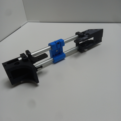
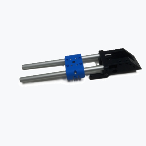
The base axis forms the foundation of the future linear axis while intentionally omitting the drive components at this stage. It consists of two aluminum tubes that serve as guide rails, two timing belt idler housings, and a tensioning element, which initially acts as a dimensional reference and will later be used to tension the timing belt.
The guide carriage (slider) is also assembled as part of this subassembly. Since the drive components are not yet installed, the slider is secured in its center position with an M3 screw.
This concept supports the modular architecture of the MidiMotionRig. Even the 2DOF configuration consists of two fully assembled linear axes and two base axes. As a result, the platform can later be expanded step by step into a 3DOF or 4DOF configuration without requiring additional base components to be printed or replaced.
Matching Components for the Basic axis
If you want to recreate the Workshopboard without spending time searching for parts, you will find the key components here that were used exactly in this setup.
The complete parts list, including dimensions, quantities, and standardized components, is also available as a PDF.
Affiliate link: As an Amazon Associate, I earn from qualifying purchases.
Step-by-Step Assembly Guide
Step 1 – Preparing the Material
First, download the technical drawing and the parts list. Both files can be found at the end of this page.
Then prepare all required components and tools for the assembly.
Step 2 – Preparing the Bearing Housings
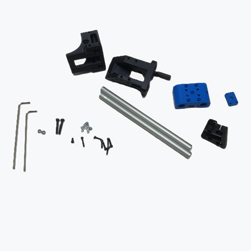
Take the Tension Bearing Housing (Pos. 1) and the Fixed Bearing Housing. Insert two M3 nuts into the designated pockets on the inside of each housing and loosely install the M3×20 screws. This keeps the nuts securely in place during the remaining assembly.
The Tension Bearing Housing can now be set aside. The next step continues with the Fixed Bearing Housing.
Step 3 – Installing the Guide Rods
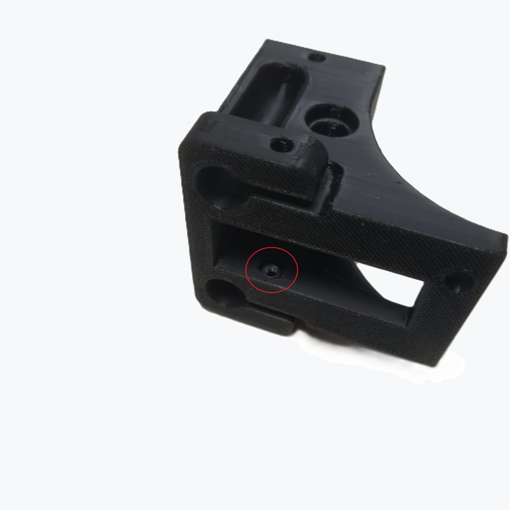
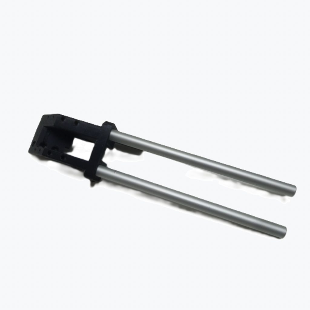
Insert the two Guidance Rods (Pos. 2) into the designated openings of the Fixed Bearing Housing until they reach the stop.
Make sure the aluminum tubes are fully inserted against the internal stops, as this position is important for the correct alignment of the axis during later assembly.
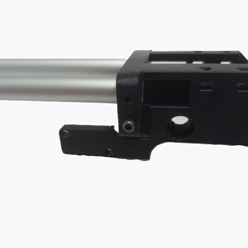
Step 4 – Preparing the Slider
To prepare the Slider (Pos. 5), first insert four M3 nuts into the designated pockets. Then install the Mounting Plate, which securely retains the nuts in their positions.
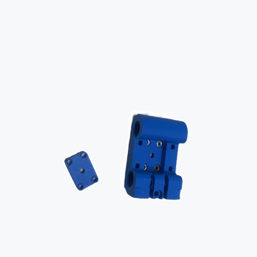
Step 5 – Securing the Mounting Plate
Secure the Mounting Plate to the Slider using one M3 nut and one M3×8 screw.
Make sure the screw protrudes only slightly beyond the nut. This prevents it from damaging the timing belt during later assembly.
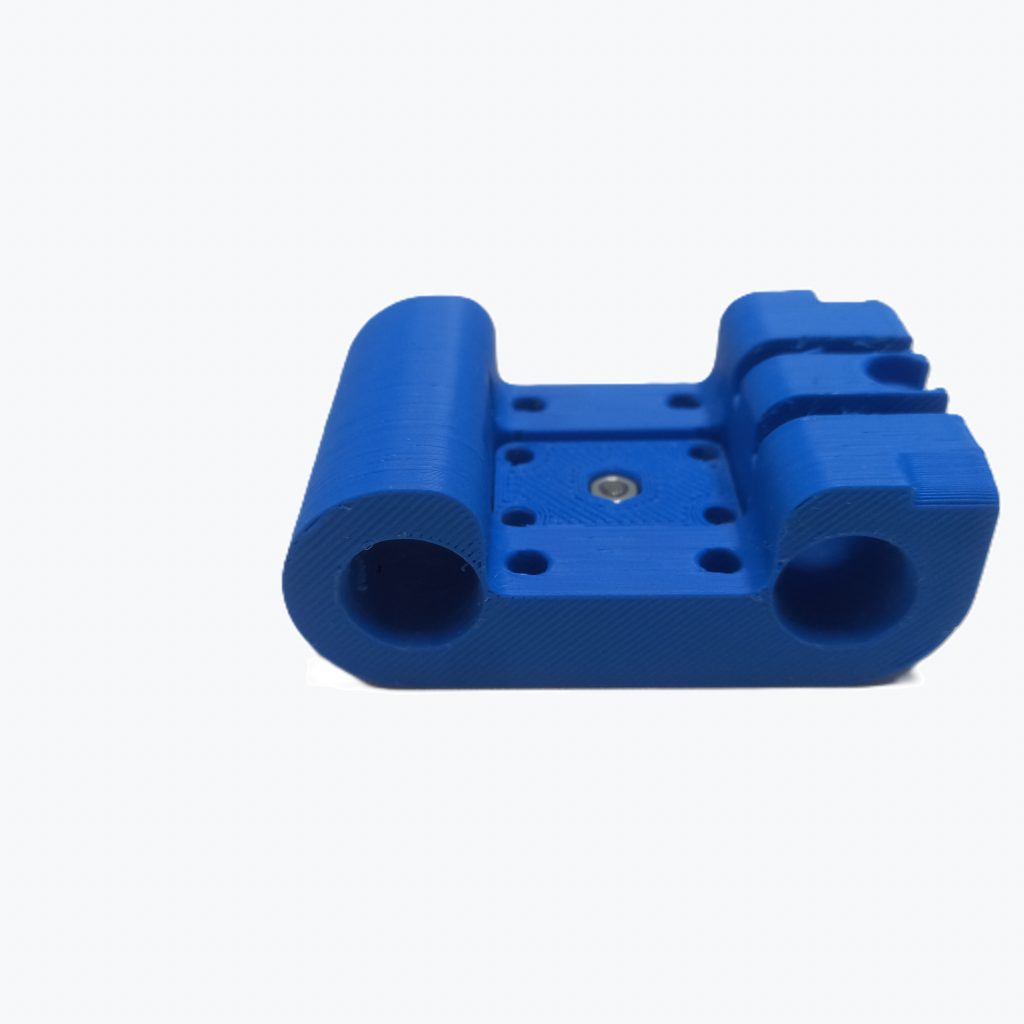
Step 6 – Installing the Locking Screw
In the next step, install the locking screw (M3×16) together with an M3 nut in the Slider.
This screw is only required for the static base axis configuration. If the assembly is being built directly as a linear axis, this step and the associated hardware can be omitted.
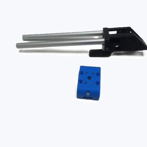
Step 7 – Installing the Slider
Slide the prepared Slider onto the two guide rods and lightly clamp it in place near the already installed bearing housing.
Note: The aluminum tubes I used were slightly oversized. To compensate, I lightly reworked the holes in the printed slider using a Ø12.4 mm countersink in a drill press. The resulting clearance is, in my experience, not critical for this application. The slider moves smoothly along the guide rods while remaining stable, without noticeable play.
Step 8 – Preparing the Mounting Clamp
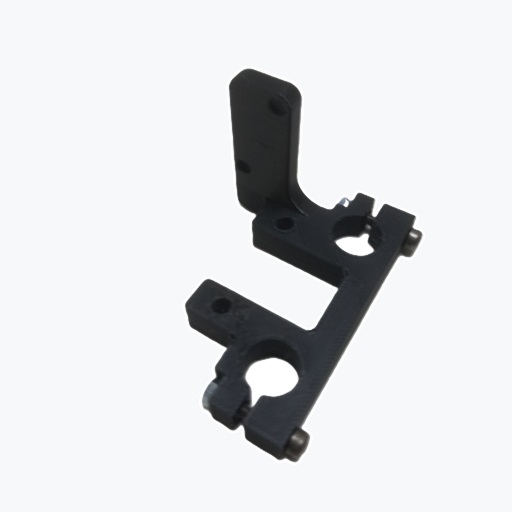
Next, preassemble the Mounting Clamp. Install two M3×20 screws with two M3 nuts, followed by two M4×25 screws with the corresponding M4 nuts.
The Mounting Clamp serves several purposes later in the project. It acts as a dimensional reference during assembly, provides a mounting point for a limit switch, and, when the base axis is upgraded to a linear axis, forms the fixed end used to tension the timing belt.
Step 9 – Installing the Mounting Clamp
Slide the Mounting Clamp onto the two guide rods. Unlike the Slider, this component may require light force during installation.
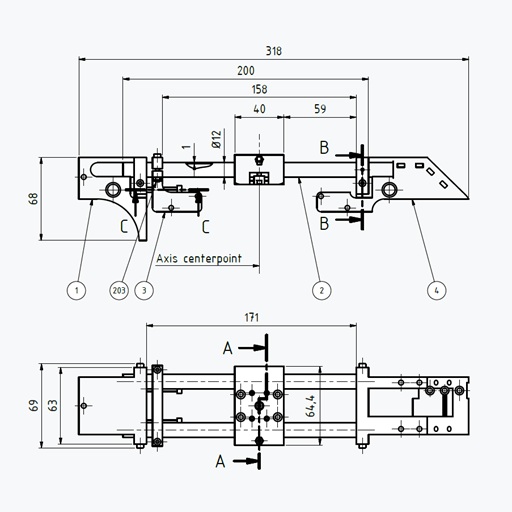
For the initial alignment, position the Mounting Clamp approximately 158 mm from the idler housing. In practice, however, it has proven more convenient to start with a rough spacing of about 160 mm and perform the final adjustment later.
Step 10 – Installing the Second Bearing Housing
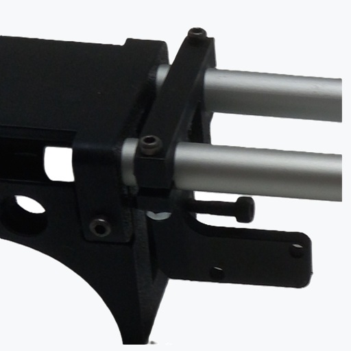
Slide the prepared Tension Bearing Housing onto the guide rods and lightly clamp it in place.
This is a good opportunity to check the movement of the Slider. It should travel smoothly along the guide rods without noticeable binding or misalignment.
Step 11 – Aligning the Assembly
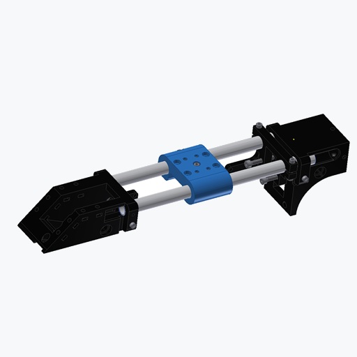
In the final assembly step, first align Position 3 and then Position 1 to their exact dimensions.
Begin by loosening the M3 screws on Position 3. Using the two M4 adjustment screws, set the component to the specified drawing dimension of 158 mm. For this task, I used a 300 mm digital caliper, which is also listed in the tools section of the parts list.
One advantage of this design is that Position 3 is supported by Position 1 during adjustment. This allows the dimension to be set very precisely using the thread pitch of the M4 screws. The adjustment screw on the limit switch side is slightly difficult to access, but using a screwdriver bit as an extension works well.
Once Position 3 has been aligned correctly, tighten the M3 screws again.
Next, loosen Position 1. In most cases, the two M4 adjustment screws will first need to be backed off slightly. Slide Position 1 by hand to just under 171 mm, then use the M4 adjustment screws to set the exact drawing dimension before tightening the screws.
Step 12 – Aligning the Slider
As the final step, align the Slider. Loosen the locking screw and set the distance to 59 mm, as specified in the drawing.
Before fixing the slider in its final position, it is recommended to check the movement of the axis one last time. If the slider moves smoothly, all dimensions are correct, and the slider has been secured, the base axis is fully assembled.
Additional Information:
Assembly drawing
Guidance rod
3D- PDF