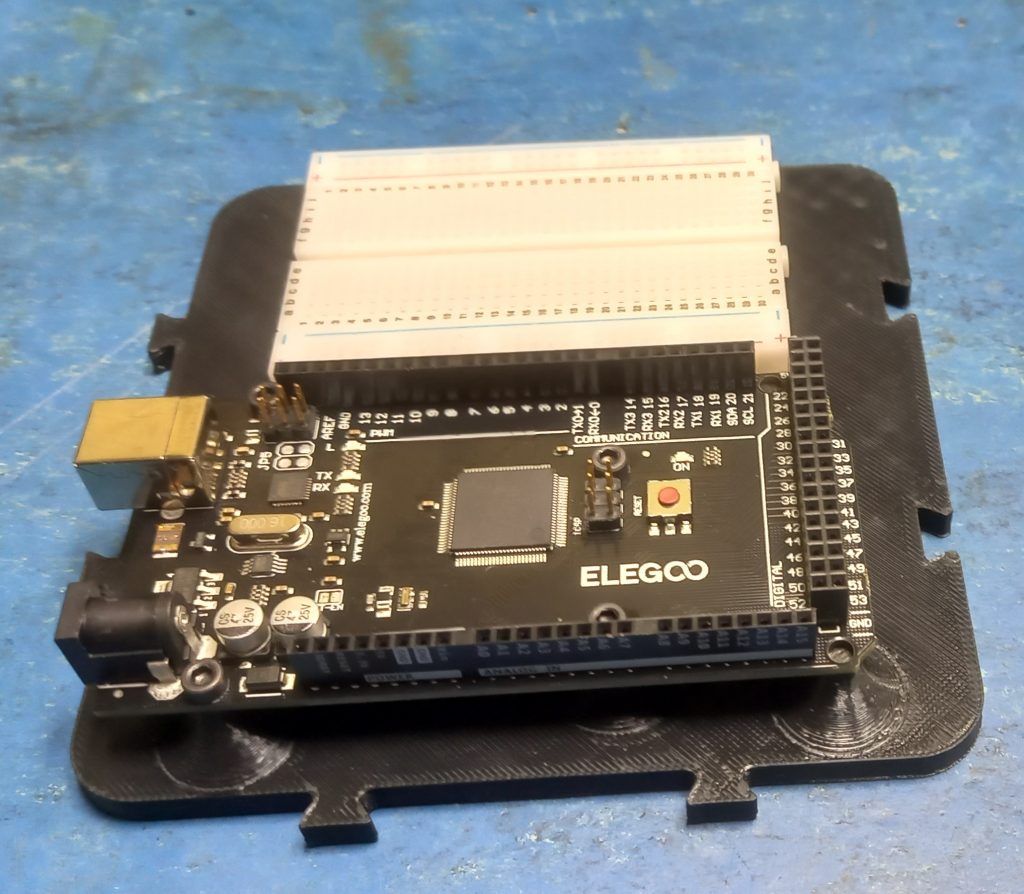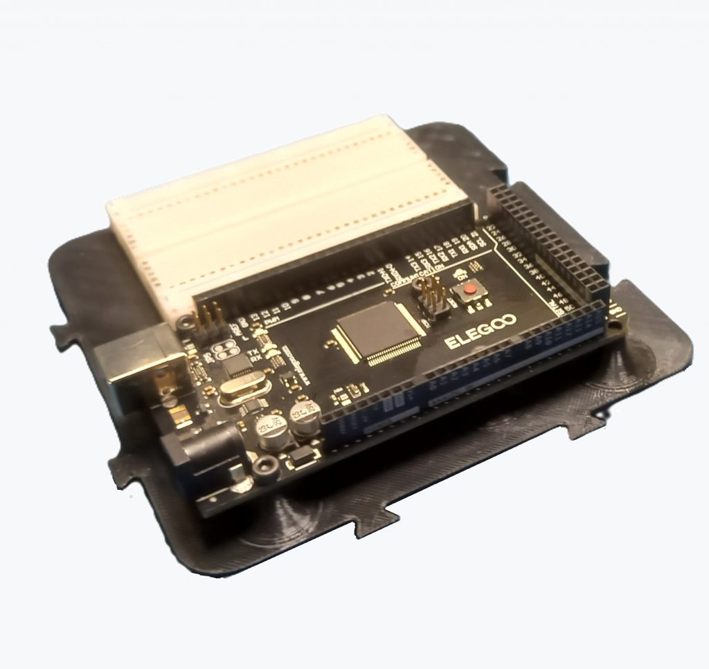
The Workshopboard serves as a stable and well-organized base for experiments and prototypes built around the Arduino Mega 2560.
The board is 3D-printed from black PLA and is intended for use both on the workbench and in modular project setups. The Arduino Mega 2560 can be securely mounted on the board. In addition, the board provides space for an AZDelivery Mini Breadboard with 400 pins, which is attached using adhesive. This makes it possible to build test circuits without components or wires shifting during work.
The board follows a consistently modular design.
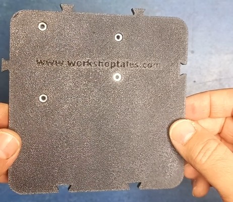
Two sides feature dovetail tabs, while the opposite sides have matching dovetail slots. Multiple Workshopboards can be connected like puzzle pieces and expanded as needed.
For fixed mounting, the board includes two diagonally positioned countersunk holes.
With overall dimensions of 124 × 124 mm, the Workshopboard remains compact while still offering enough space for the controller, breadboard, and clean, practical work.
All mounting hardware required for assembly is listed in the parts list below.
Matching Components for the Workshopboard
If you want to recreate the Workshopboard without spending time searching for parts, you will find the key components here that were used exactly in this setup.
Arduino Mega 2560 R3 https://amzn.to/47vPfhx
Mini Breadboard 400 PIN https://amzn.to/4ccsZMj
Cylinder head bolt M3x12 https://amzn.to/410AlfK
Nut M3 https://amzn.to/47tbWmu
Affiliate link: As an Amazon Associate, I earn from qualifying purchases.
3D-Data: Thingiverse / Printables
Assembly
The assembly of the Workshopboard can be completed in just a few steps.
All components listed in the parts list are required for the build.
Step 1 – Printing the base plate
First, the print file is downloaded from Printables and the base plate is 3D-printed.
The following print settings are sufficient:
Layer height: 0.2 mm
Infill: 15 %
This results in a stable foundation for the remaining assembly.
Step 2 – Inserting the nuts
Next, the nuts are inserted from the back into the four designated recesses and pressed in flush.
Depending on print tolerances, it may be helpful to gently pull the nuts into place using a screw before mounting the Arduino.
This ensures they sit cleanly and do not tilt.
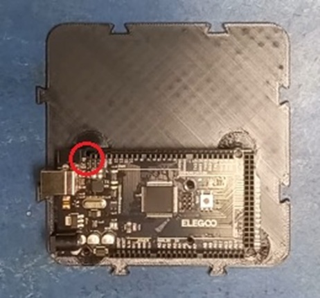
Step 3 – Mounting the Arduino Mega
The Arduino Mega 2560 is then mounted to the Workshopboard using four M3×12 socket head screws (DIN 912).
Note:
Depending on the population of the Arduino board, one screw position (marked in red) may collide with an SMD component.
In this case, mount carefully and leave out the screw if necessary.
Step 4 – Attaching the breadboard
Finally, the protective film is removed from the adhesive strip on the mini breadboard, and the breadboard is pressed onto the designated area.
With this, the Workshopboard is ready for use in experiments and modular prototype setups.