The Arduino runs with the sketch shown here in the grey box.
After installing Arduino IDE 2.3.8 on your computer, open it, select the correct COM port, and then you can verify and upload the sketch.
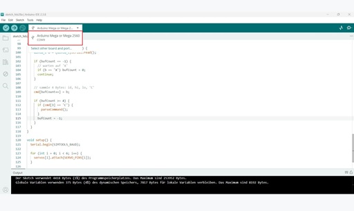
Simply copy the code from the grey box into the IDE, verify it, and upload — done.
/*
  SimTools 2.4 -> 6 Servos (Arduino Mega 2560)

  SimTools Interface Settings:
    BitsPerSec: 57600
    Data Bits: 8
    Parity: None
    Stop Bits: 1
    Output Type: Binary
    Bit Range: 10

  Startup:   XS00C
  Runtime:   X1<Axis1a>CX2<Axis2a>CX3<Axis3a>CX4<Axis4a>CX5<Axis5a>CX6<Axis6a>C
  Shutdown:  XE00C

  Servos on A0..A5 (used as digital pins 54..59 on Mega).
*/

#include <Arduino.h>
#include <Servo.h>

static const uint32_t SIMTOOLS_BAUD = 57600;

// Servo pins: A0..A5
static const uint8_t SERVO_PINS[6] = {A0, A1, A2, A3, A4, A5};

// Servo movement range (mechanisch sicher anpassbar)
static const int SERVO_MIN_DEG = 0;
static const int SERVO_MAX_DEG = 180;

// Mittelwert von SimTools (10-bit)
static const int CENTER_10BIT = 512;

// --- Servo objects
Servo servos[6];
int lastDeg[6] = {90, 90, 90, 90, 90, 90};

// --- Parser buffer: [id, hi, lo, 'C']
uint8_t cmd[4];
int bufCount = -1;

static inline int clampInt(int v, int lo, int hi) {
  if (v < lo) return lo;
  if (v > hi) return hi;
  return v;
}

// Map 0..1023 -> Servo degrees
static int map10bitToServoDeg(int v10) {
  v10 = clampInt(v10, 0, 1023);
  long deg = map(v10, 0, 1023, SERVO_MIN_DEG, SERVO_MAX_DEG);
  return (int)deg;
}

// Set all servos to center
static void setAllCenter() {
  for (int i = 0; i < 6; i++) {
    lastDeg[i] = map10bitToServoDeg(CENTER_10BIT);
    servos[i].write(lastDeg[i]);
  }
}

// Optional: Stop = Position halten
static void stopServosHold() {
  // nichts tun (Servos halten letzte Position)
}

// Parse one completed command frame
static void parseCommand() {
  const uint8_t id = cmd[0];

  if (id == 'S') {            // Start
    setAllCenter();
    return;
  }

  if (id == 'E') {            // End
    stopServosHold();
    return;
  }

  if (id >= '1' && id <= '6') {
    int idx = (int)(id - '1');

    // 10-bit Wert zusammensetzen
    int v10 = ((int)cmd[1] << 8) | (int)cmd[2];

    int deg = map10bitToServoDeg(v10);

    // Nur schreiben wenn geändert (reduziert Jitter)
    if (deg != lastDeg[idx]) {
      lastDeg[idx] = deg;
      servos[idx].write(deg);
    }
  }
}

static void serialWorker() {
  while (Serial.available() > 0) {
    uint8_t b = (uint8_t)Serial.read();

    if (bufCount == -1) {
      // warten auf 'X'
      if (b == 'X') bufCount = 0;
      continue;
    }

    // sammle 4 Bytes: id, hi, lo, 'C'
    cmd[bufCount++] = b;

    if (bufCount >= 4) {
      if (cmd[3] == 'C') {
        parseCommand();
      }
      bufCount = -1;
    }
  }
}

void setup() {
  Serial.begin(SIMTOOLS_BAUD);

  for (int i = 0; i < 6; i++) {
    servos[i].attach(SERVO_PINS[i]);
  }

  setAllCenter();
}

void loop() {
  serialWorker();
}
Note: I am not a professional at writing Arduino code. My approach was to describe and structure the sketch step by step as precisely as possible with ChatGPT, so that everything works as planned in the end. Of course, anyone interested is welcome to adapt or expand the code.