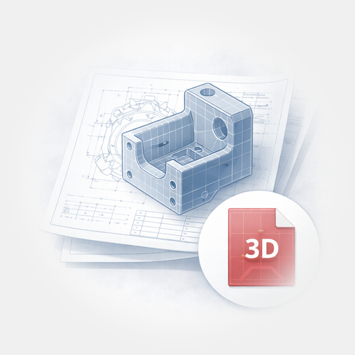
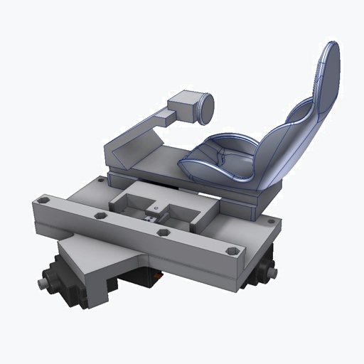
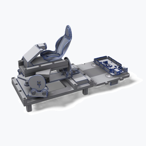
Mechanical Structure
Basic Principle
The construction is based almost entirely on 3D-printed parts made from PLA. Only a small number of standard hardware-store components are required in addition. This keeps the project accessible even with a basic entry-level 3D printer.
Depending on print quality, it may be necessary to slightly adjust or clean up some fits. If needed, cyanoacrylate glue can be used to secure certain parts.
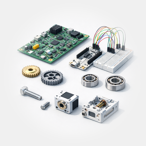
Matching Components for the Workshopboard
If you want to recreate the Workshopboard without spending time searching for parts, you will find the key components here that were used exactly in this setup.
The complete parts list, including dimensions, quantities, and standardized components, is also available as a PDF.
Affiliate link: As an Amazon Associate, I earn from qualifying purchases.
Tool List
- Hex keys SW 2,5 and SW 4
- Open-ended wrench SW 8
- Small Phillips screwdriver
- Side cutters (for fine cuts)
- Multitool (e.g. Dremel or Proxxon)
- ø1,8mm HSS-drill
- Optional flat file (smooth)
- 3D printer
The selection of tools was deliberately chosen so that they are typically available in a standard hobby workshop.
Step-by-Step Instructions
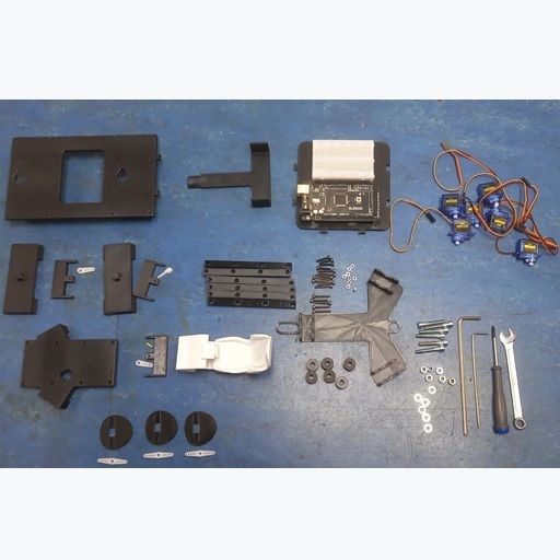
All parts from the parts list must be fully available and ready for assembly of the 6-axis system.
1.)
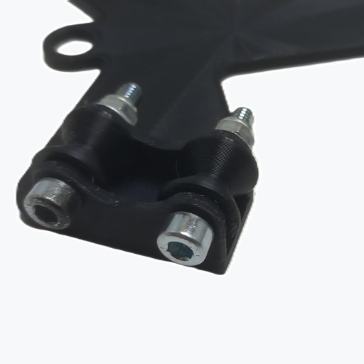
Mount the GS-00-13 rollers on the GS-00-14 base plate using the M5 × 25 screws, washers, and lock nuts.
Tighten the lock nuts so that the rollers are free of play but can still rotate smoothly.
2.)
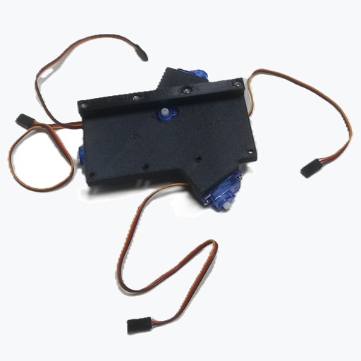
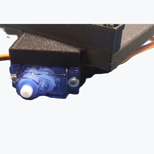
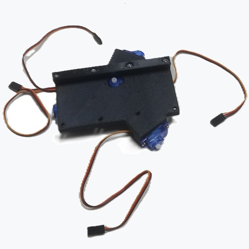
Take the GS-00-05 base plate and mount the servo for forward/backward motion (surge) in the center.
Do not attach the control horn yet.
If necessary, slightly ream the two mounting holes for the servo with a Ø1.8 mm drill bit before screwing in the supplied screws. This also applies to all following servos.
Do not attach the control horns yet.
3.)
Mount the servos for axes 2–4 as well.
Make sure to pay attention to the correct alignment.
4.)
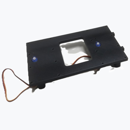
Take the GS-00-17 base plate and mount the two servos for sideways motion (sway) and yaw.
Do not attach the control horns yet.
5.)
Next, insert 4 M3 nuts into each of the GS-00-06 strips.
Make sure the nuts are properly seated and flush.
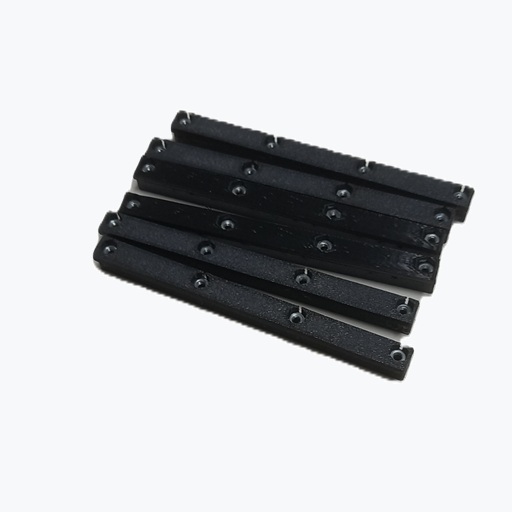
6.)
Screw one of the GS-00-06 strips to the GS-00-05 base plate on the servo side.
7.)
Screw two more GS-00-06 strips to the GS-00-17 base plate, also on the servo side.
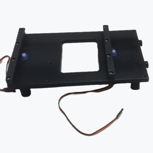
8.)
Insert the GS-00-20 support into the GS-00-17 base plate.
If needed, secure it with a small amount of cyanoacrylate glue.
9.)
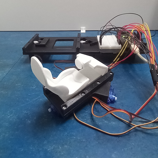
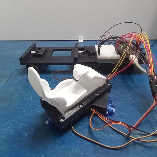
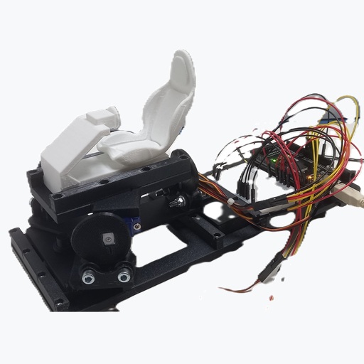
Place the Workshopboard and connect servos 1 and 6.
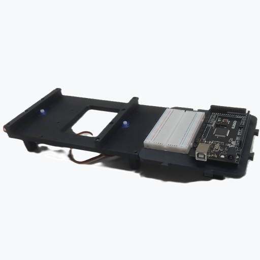
10.)
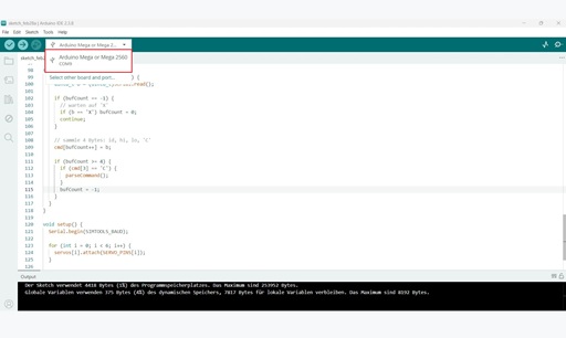
Open the Arduino IDE, connect the Arduino, and create a new sketch.
Copy in the template sketch, then verify and compile it.
11.)
Establish the connection with SimTools under the Interface Settings tab.
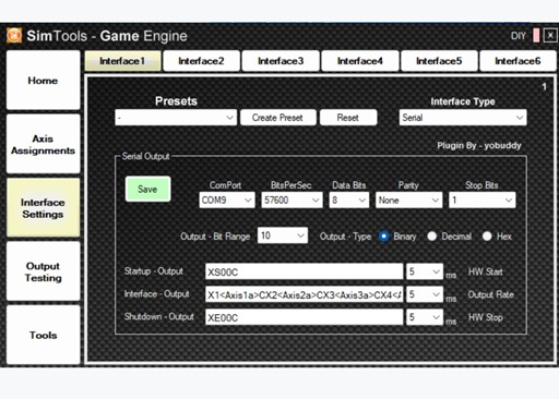
The following settings are required:
Interface Type: Serial
ComPort: COM-Port des Arduino aus der Arduino-IDE übernehmen
BitsPerSec: 57600
Data Bits: 8
Parity: None
Stop Bits: 1
Output Bit Range: 10
Output Type: Binary
Start Output: XS00C
Interface Output: X1<Axis1a>CX2<Axis2a>CX3<Axis3a>CX4<Axis4a>CX5<Axis5a>CX6<Axis6a>C
Shutdown Output: XE00C
12.)
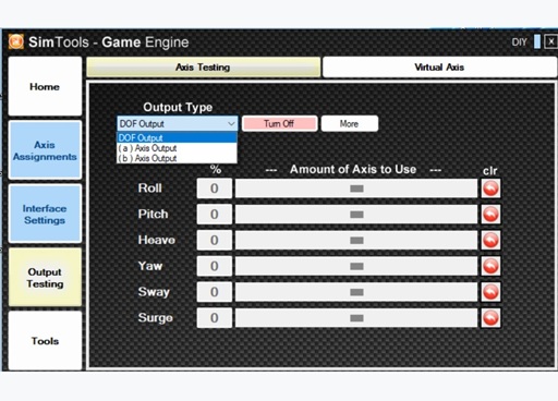
Once everything is set up, the axis test can be performed.
Switch to AxisA in the test environment to control the individual outputs directly.
Finally, move all servos to the center position.
13.)
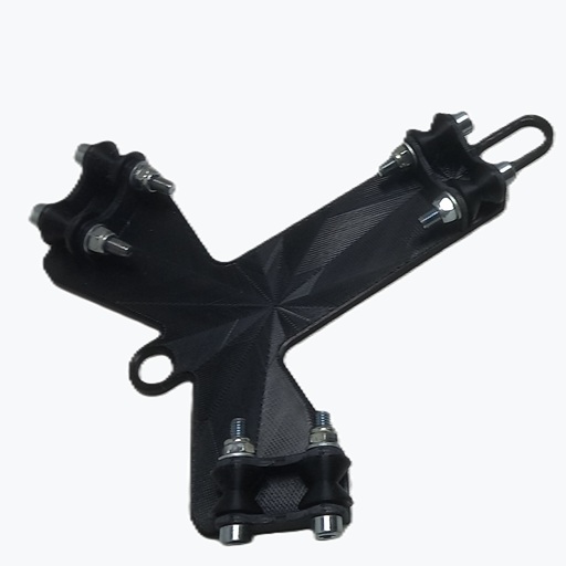
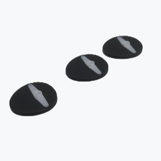
Mount the cam discs with the arrow pointing down onto the corresponding three servos on the GS-00-05 plate.
14.)
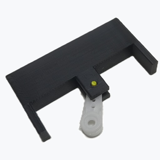
Connect the three GS-00-04 sliders to a short control horn (total length 22 mm).
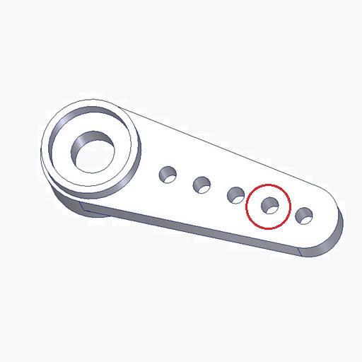
The second hole must be slightly enlarged using a small round file, a Ø1.8 mm drill bit, or a multitool so that a Ø1.75 mm filament can pass through easily.
If necessary, also adjust the holes in the slider.
The filament should fit snugly but be able to be inserted without force.
Now mount the control horn together with the slider on the servo and trim any excess filament flush.
15.)
Now mount the prepared sliders in the center position on the pre-assembled GS-00-05 and GS-00-17 plates.
16.)
Slide the seat from the side over the slider onto the GS-00-05 plate.
Then fasten the missing strip with 4 M3 × 12 screws.
The seat should be able to move slightly and must not fit tightly on the slider or between the strips.
If this is the case, the first axis is complete.
Note:
If only 3 axes are being built, the seat can be shimmed with a piece of paper and clamped with the side strips.
17.)
Snap the 36 mm control horns into the GS-00-21 cam discs.
With the correct tolerance, they should fit in with light pressure and sit firmly afterwards.
The control horns can also be secured with 1–2 drops of cyanoacrylate glue.
The data for the cam discs is also available in STEP format, in case they need to be adapted to differently shaped control horns.
18.)
Repeat step 16 with the GS-00-18 sliders on the GS-00-17 plate and also mount the two missing strips.
19.)
Place the prepared GS-00-14 plate onto the completed GS-00-17 plate.
20.)
Assembly Completion:
Position the pre-assembled axes 1–4 onto the rollers.
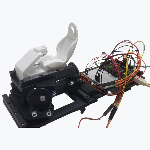
The Nano Motion Rig is now complete.
Note:
The system can also be built as a 3-axis or 4-axis setup.
For 4 axes, omit the assembly on the GS-00-17 plate.
For 3 axes, also omit the Surge function (seat moves forward/backward) according to the instructions.
Additional Datas:
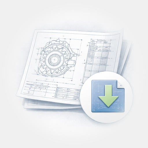
Drawing
PDF-Bill of Material